Frequently asked questions
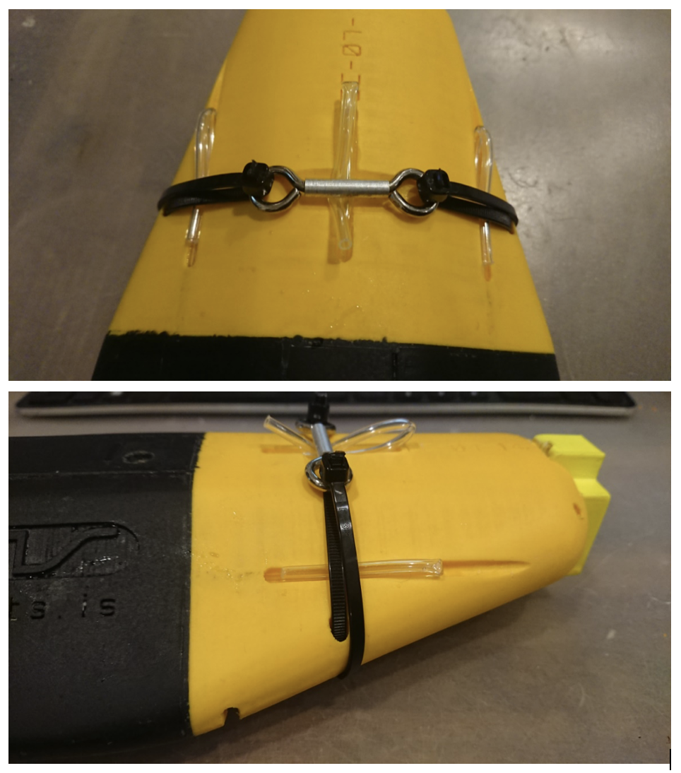
I attached 2 pics of a rigged up suction cup release system which should give you an idea of how it works.
The tag in the pic is slightly different, but same basic system:
In the groove on top that goes across is where the GTR sits. It is held in place by cable ties.
The cable ties loop around the tag and are held in place by the holes on the side (prevent them from sliding forward or backwards).
Do not use those holes on the side as anchor point for the cable ties.
To actually ‘arm’ the unit and make the suction cups stick, the tubes coming from the suction cups must be kinked over so they are sealed and the ends passed through under the cable ties again so they are held down by them.
Once the GTR corrodes away, the cable ties loosen and the tubes can flip open, so water gets in and the suction cups release.
GTRs can be ordered from here:
underseareleases.com/timetempchart.htm
Turn on the CATS tag WiFi using the methods outlined in Part 1 (swipe once and wait for a solid blue light). Once the tag has successfully connected, click the “live view” button and wait for values to appear in the “live data” box.

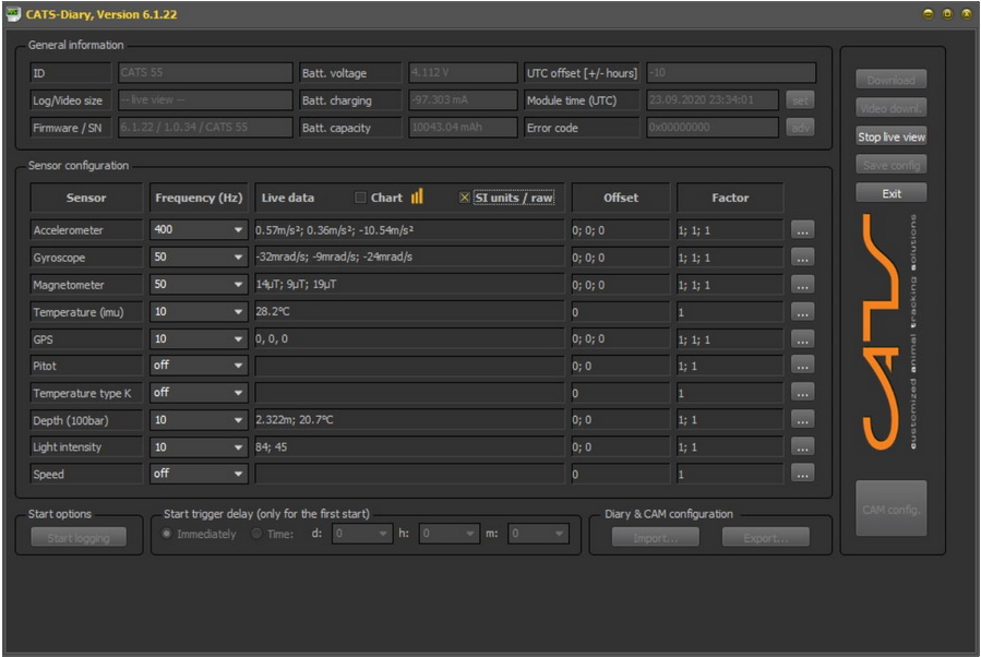
These values correspond to each of the three axes of the tag (x-axis, y-axis, and z-axis). When the tag is on a flat surface in a horizontal position, the x and y axes of the accelerometer should be close to O m/s2 and the z axis should be close to -9.8 m/s2 to correspond with the pull of gravity upon the tag. These orientations are shown in below.
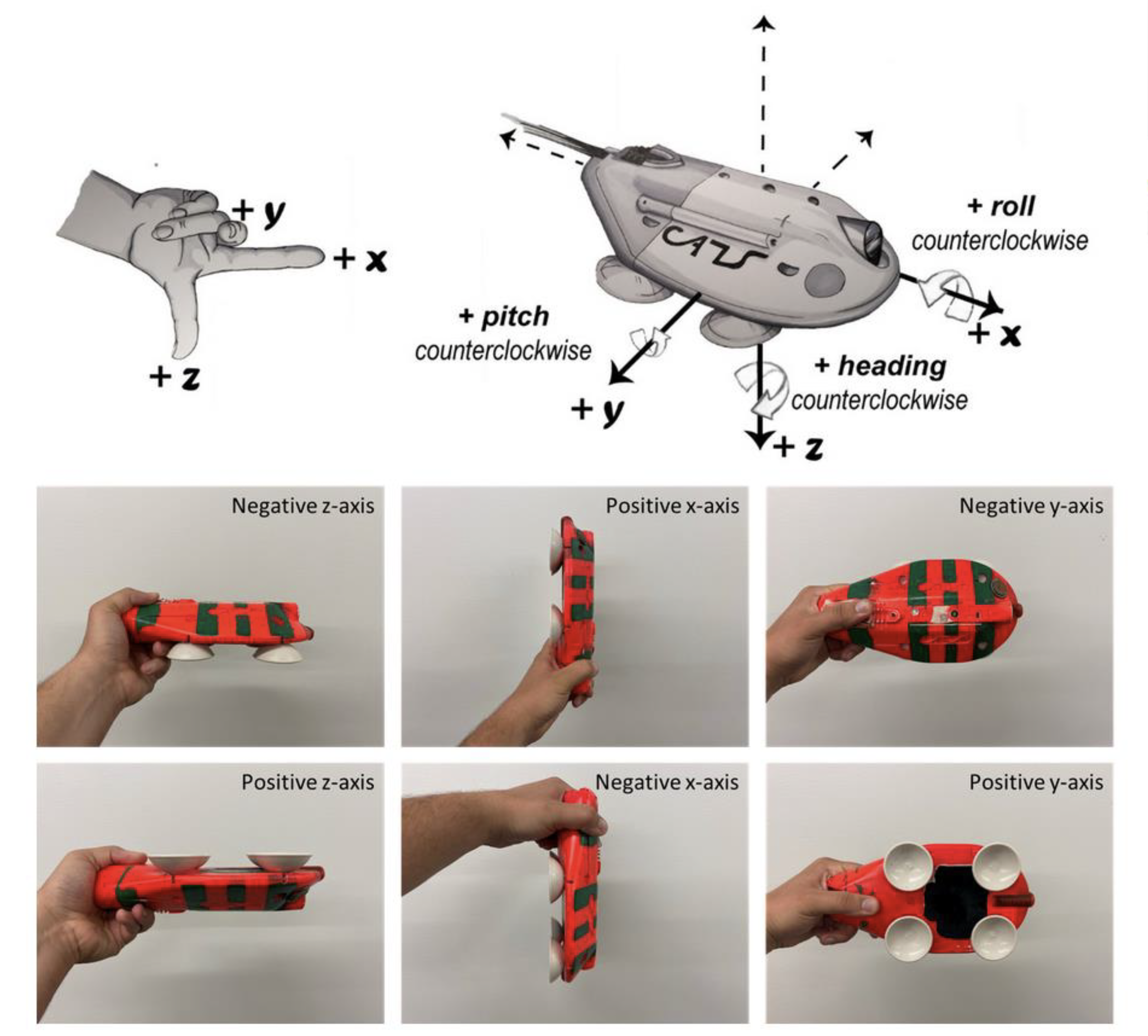
For the magnetometer, the three axis will change in relation to magnetic north. When an axis is pointed towards the magnetic north pole (depending on your position on the globe, this point may be aimed downward and “inside” the earth), it will show its maximum (or minimum) value. See the image below for a compilation of these orientations.
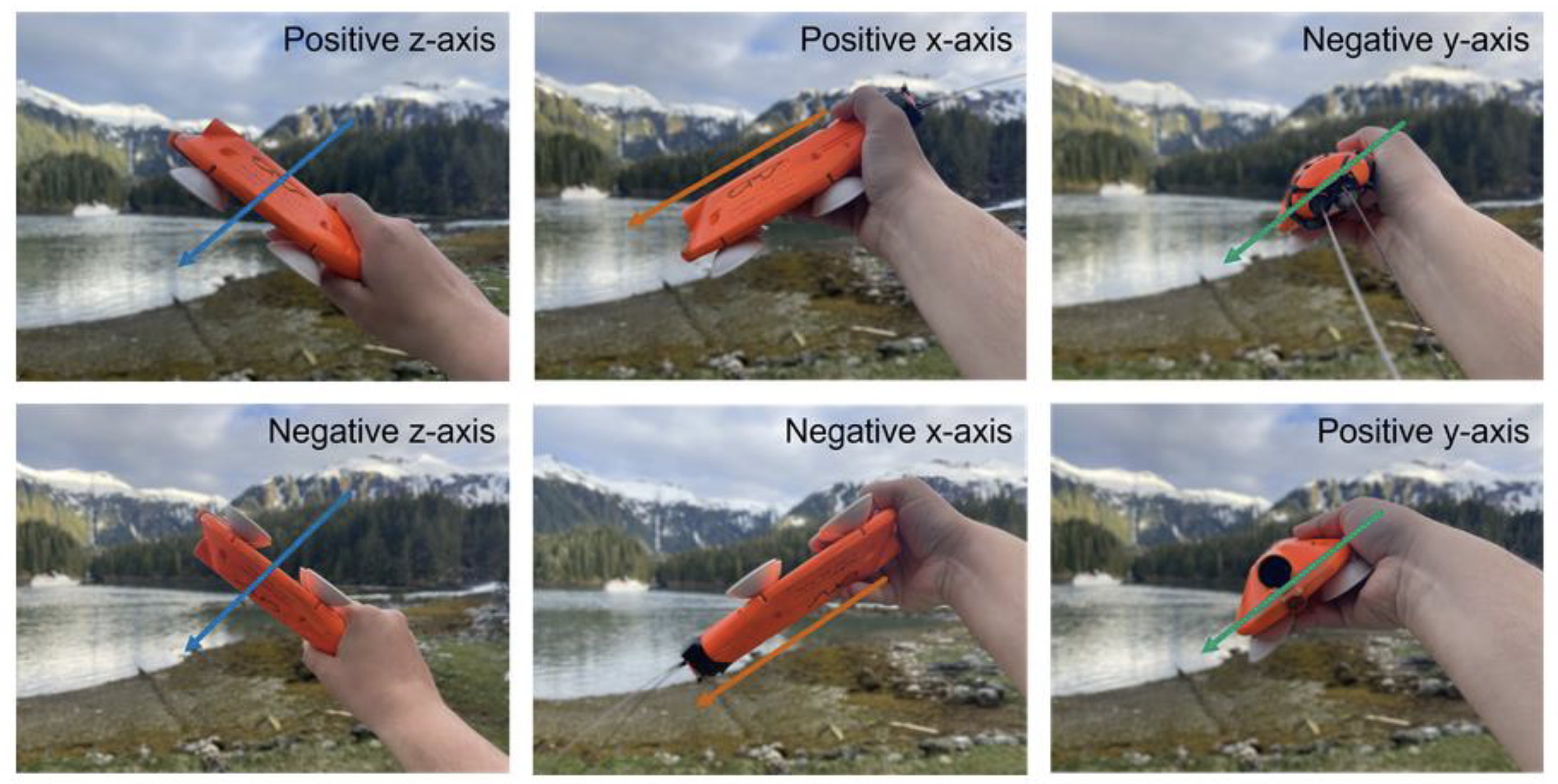
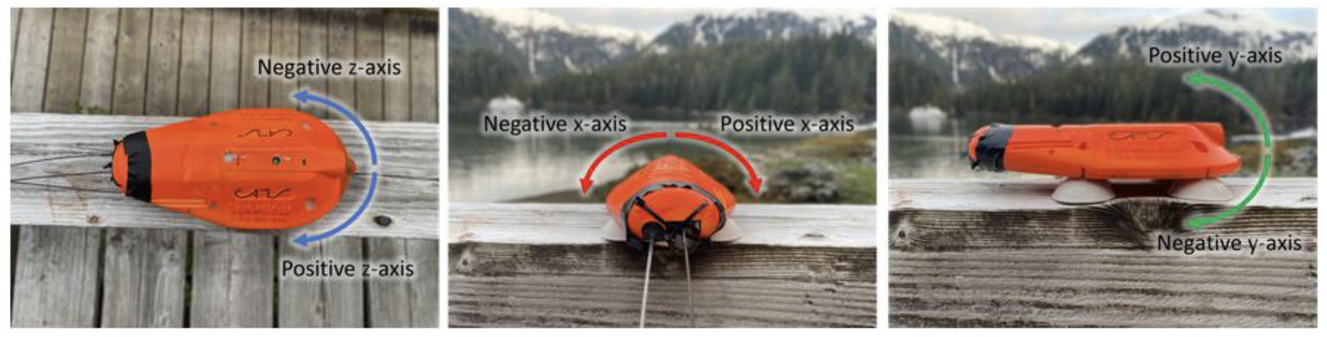
For the gyroscope, rotational movement of the tag will determine values. Direction of the rotation will determine if the values are positive or negative. A rightward roll from a horizontal resting position should display positive x values, while a leftward roll from the same starting position should display negative x values. Rolling the tag upward along its short axis (camera rolling towards the sky and over backwards) should display positive y values, with a roll downward displaying negative y values. Finally, yawing (spinning) the tag to the left from a horizontal resting position should display negative z values, while yawing the tag to the right should display positive z values. See the image below for a schematic of these orientations.
It is possible that the order of these values will be different from the images shown above. If this is the case, the axis conventions for your tag may be different from those described above and you will want to check by running a series of quick diagnostic tests. For the accelerometer, some potential diagnostic movements include:
1. Flipping the tag onto its back and resting it flat on the table (Fig X; Bottom Left Image). This should constitute a change in the z-axis from negative to positive ~ 10 or vice versa, with no change in either the x or y axes.
2. Pointing the nose of the tag upwards or downwards, perpendicular to the table, should constitute a change in the x and z axes of the tag, with no change in the y axis (Fig X; Center Images). The x-axis will shift from -0 to either positive or negative -10 and the z-axis will shift from either positive or negative -10 to -0.
3. Rolling the tag until one side is in the air will constitute a change in they and z axes, with no change in the x-axis (Fig X; Right Images). The y-axis will shift from ~O to either positive or negative ~ 10 and the z-axis will shift from either positive or negative ~10 to ~0.
Be sure to perform diagnostic movements for all three of your inertial sensors (accelerometer, magnetometer, gyroscope) using the default axis conventions listed and shown above as a guide. While performing these diagnostics, assume that [x y z) is the default axis convention matrix. Any deviations from the default axis conventions should be reflected in your axis convention matrices. So, if you find that x values are positive when the tag is facing downward (center bottom image above), you would likely have an accelerometer axis convention of [-x y z]. If you found that they values are negative and the x and z values are zero when the tag is sitting flat and horizontal on a surface (top left image above), and also found that the z values are negative and x and y values are zero when the tag is turned with its right side down (top right image above), you would know that they and z axes are switched and you would likely have an accelerometer axis convention of [x z yJ.
Take some time to experiment with these diagnostics and get a sense for the axes of the tag. If you would like to see these values in a graphical forma~ check the -chart” box near the middle of UI screen next to the yellow graphical icon. This will produce a new window with three graphs showing a running waveform for each axis of the accelerometer, gyroscope, and magnetometer.